Cub3D is basically so_long’s big brother, as it shares many core features like flood filling a map, handling key press events, and rendering images to the screen. However, as we’ll see later on, there are many functionalities which have completely changed in comparison.
We managed to get ~750 fps on a 12th Gen Intel i7 with 16GB of RAM running on Ubuntu 22.04.2 LTS (or ~50 with Valgrind). Just to give you an idea of the performance you can achieve.
Understanding Ray Casting
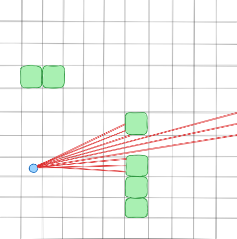
Ray casting lies at the heart of Cub3D, enabling the creation of a 3D environment using 2D graphics techniques. By simulating the projection of rays from the player’s viewpoint, we can achieve the illusion of depth and perspective. With a bit of fancy math, we can transform those rays into visible walls, and finally — with a bit more math — into textures.
Here is a graphical example which hopefully illustrates the idea a bit better.
Implementation Details
Although I’ve been referring to ray casting as the sole culprit to this project, it’s not the only piece of the puzzle! You will have to implement a lot of other functionalities, such as handling image buffers and texture colouring, to create a fully functional 3D environment.
Setting Up the Environment
Before delving into the implementation, you’ll need to set up your development environment. Cub3D leverages the MinilibX library for graphics rendering. Ensure that you have the necessary tools installed and familiarize yourself with the project’s requirements and constraints.
If you need help with this, I built a tool called 42-cli which streamlines the MLX installation process for you. You can checkout how I implemented this in this article (works on both MacOS and Linux).
The Math Behind Ray Casting
Now that we have a basic understanding of the project, let’s delve deeper into the core algorithm responsible for raycasting. Below, we’ll explore the implementation details of the raycasting algorithm, focusing on key functions and their roles in rendering the 3D environment.
I want to emphasize that understanding the math behind raycasting is crucial to the project’s success. I recommend reading through the resources provided at the end of this article to gain a deeper understanding of the concepts involved.
Step 1: Calculating the Ray Direction
The first step in the raycasting algorithm is to calculate the direction of the ray based on the player’s position and orientation. This involves determining the angle of the ray relative to the player’s view and converting it into a unit vector.
int x = 0;
while (x < WIN_WIDTH)
{
	double camera_x = 2 * x / (double)WIN_WIDTH - 1;
	double ray_dir_x = dir_x + plane_x * camera_x;
	double ray_dir_y = dir_y + plane_y * camera_x;

	// ...
Here we calculate the direction of the ray based on the player’s direction (dir_x and dir_y), the player’s plane (plane_x and plane_y) and the camera plane. The camera_x variable represents the x-coordinate of the ray in camera space, which is then used to calculate the ray’s direction vector.
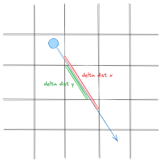
Step 2: Calculating the Delta Distance
The next step in the raycasting algorithm is to calculate the delta distance between two consecutive x or y intersections with a grid line. This is done by determining the distance the ray must travel to reach the next grid line in the x or y direction.
	// ...

	int map_x = (int)pos_x;
	int map_y = (int)pos_y;

	double delta_dist_x = fabs(1 / ray_dir_x);
	double delta_dist_y = fabs(1 / ray_dir_y);

	// ...
This gives us the distance the ray must travel to reach the next grid line in each direction. Note here that the pos_x and pos_y both refer to the player’s position.
Step 3: Calculating the Step and Initial Side Distances
Now we need to calculate the step_x, step_y and the initial side distances for the ray. The step_x and step_y variables determine the direction in which the ray moves through the grid.
The side_dist_x and side_dist_y variables represent initially the distance the ray must travel from its current position to the next grid line in the x or y direction. Later these variables will be updated with the delta distance as the ray moves through the grid.
	// ...

	int step_x;
	int step_y;

	double side_dist_x;
	double side_dist_y;

	if (ray_dir_x < 0)
	{
		step_x = -1;
		side_dist_x = (pos_x - map_x) * delta_dist_x;
	}
	else
	{
		step_x = 1;
		side_dist_x = (map_x + 1.0 - pos_x) * delta_dist_x;
	}
	if (ray_dir_y < 0)
	{
		step_y = -1;
		side_dist_y = (pos_y - map_y) * delta_dist_y;
	}
	else
	{
		step_y = 1;
		side_dist_y = (map_y + 1.0 - pos_y) * delta_dist_y;
	}

	// ...
Step 4: Performing Digital Differential Analysis
The next step in the raycasting algorithm is to perform Digital Differential Analysis (DDA) to determine the distance to the next grid line in the x or y direction. This involves stepping through the grid and calculating the distance to the next grid line in each direction. We also take note of the side of the wall we hit (0 for x, 1 for y).
Once we hit a wall (here defined as '1', but you might define it otherwise), we break out of the loop.
	// ...

	int side;

	while (42)
	{
		if (side_dist_x < side_dist_y)
		{
			side_dist_x += delta_dist_x;
			map_x += step_x;
			side = 0;
		}
		else
		{
			side_dist_y += delta_dist_y;
			map_y += step_y;
			side = 1;
		}
		if (map[map_x][map_y] == '1')
			break;
	}

	// ...
Step 5: Calculating the Wall Height
The final step in the raycasting algorithm is to calculate the height of the wall based on the distance to the wall and the player’s view.
This involves determining the height of the wall based on the distance to the wall and the player’s view angle.
We first need to determine the distance to the wall, from which we can derive the draw start and end positions.
	// ...

	double wall_dist;

	if (side == 0)
		wall_dist = (map_x - pos_x + (1 - step_x) / 2) / ray_dir_x;
	else
		wall_dist = (map_y - pos_y + (1 - step_y) / 2) / ray_dir_y;

	int line_height = (int)(WIN_HEIGHT / wall_dist);

	int draw_start = -line_height / 2 + WIN_HEIGHT / 2;
	if (draw_start < 0)
		draw_start = 0;

	int draw_end = line_height / 2 + WIN_HEIGHT / 2;
	if (draw_end >= WIN_HEIGHT)
		draw_end = WIN_HEIGHT - 1;

	if (side == 0)
		wall_x = pos_y + wall_dist * ray->dy;
	else
		wall_x = pos_x + wall_dist * ray->dx;
	wall_x -= floor(wall_x);

	// ...
Handling the Textures
In so_long, we simply rendered our images using the built-in function from the MLX. However, as we are now in a 3D world, we need to compute which pixels get rendered ourselves. For this, we can simply discard our textures after initialisation, after storing them in a buffer. The buffer will be an array of integers, where each integer represents the colour of a pixel.
I found the best way to do this is to have the following data type.
#define NUM_TEXTURES 4

typedef struct s_data
{
	// ...
	int *texture_buffer[NUM_TEXTURES];
} t_data
So imagine you have a texture of 64x64, the size of a texture_buffer[n] will be sizeof(int) * 64 * 64. To access a pixel, you can use the following formula: texture_buffer[n][y * 64 + x]. This skips y rows by multiplying the width of the texture, and then adds x to get the pixel.
To get a pixel value from a MLX image pointer, you need to use the mlx_get_data_addr function, and you can access a pixel like this: img->addr[y * img->width + x]. I recommend reading the docs for this function to understand how and why it works.
The Pixel Map
We used a pixel map, which represents the pixels you see in the window on a 1-1 scale. So right after a ray is casted and the wall height is determined, we calculate each pixel for that given ray.
After the whole ray casting is performed, we can draw all the non-zero values in the map. All zero values are drawn depending on the ceiling or floor colour.
Note: This is not our solution. I will link the explanation and the maths below.
This is a small snippet of how you can update the pixel map, but more importantly, how you can derive the colour of a pixel from a texture.
#define TEXTURE_SIZE 64

typedef enum e_cardinal_direction
{
	NORTH = 0,
	SOUTH = 1,
	WEST = 2,
	EAST = 3
}	t_cardinal_direction;

t_cardinal_direction dir;
int tex_x;
int color;
double pos;
double step;

dir = ft_get_cardinal_direction();
tex_x = (int)(wall_x * TEXTURE_SIZE);

if ((side == 0 && ray_dir_x < 0) || (side == 1 && ray_dir_y > 0))
	tex_x = TEXTURE_SIZE - tex_x - 1;

step = 1.0 * TEXTURE_SIZE / line_height;
pos = (draw_start - WIN_HEIGHT / 2 + line_height / 2) * step;
while (draw_start < draw_end)
{
	pos += step;
	color = (texture_buffer)[dir][TEXTURE_SIZE * ((int)pos & (TEXTURE_SIZE - 1)) + tex_x];

	if (dir == NORTH || dir == SOUTH)
		// add some shading to the north and south walls
		color = (color >> 1) & 0x7F7F7F;
	if (color > 0)
		// your pixel map (int** in this case)
		pixels_map[draw_start][x] = color;

	draw_start++;
}
Optimising Performance
Like the above example with our image manipulation, leveraging MLX’s image functionality instead of drawing each pixel individually is a massive perf boost. We also do this to avoid slow renders and jagged re-renders. This is a small snippet to help you get started:
t_img image;

image.img = mlx_new_image(mlx_ptr, WIN_WIDTH, WIN_HEIGHT);
if (image.img == NULL)
		return;
image.addr = (int *)mlx_get_data_addr(image.img, &image.bpp,
	&image.line_length, &image.endian);

// assign RGB value to a pixel
image.addr[y * (image.line_length / 4) + x] = 0x00FF00;
So instead of drawing each pixel individually, you can assign the colour to the pixel in the image buffer, and then draw the whole image to the screen at once. This prevents the screen from flickering and speeds up the rendering process.
Common Mistakes
- Not understanding the math will make debugging a nightmare. Try to understand at least a small part of it.
- Make sure you can move with a continuous key press — I don’t want to click
Wa thousand times… - Implementing variable move speed and rotation speed. It will prevent your program from running like the speed of light on X’s computer, and as slow as a snail on Y’s computer.
- Make moving and rotating smooth. It’s not a requirement, but it’ll wow your peers.
Conclusion
Cub3D is a fun project, and I hope this article cleared a few questions up and guided you in the right direction. Happy coding!
Herbie ✌️